
IT News · @itnewsbot
3601 followers · 269752 posts · Server schleuss.onlineMinimizing Stress on a Coin Cell Battery - When it comes to powering tiny devices for a long time, coin cell batteries are th... - https://hackaday.com/2023/08/10/minimizing-stress-on-a-coin-cell-battery/ #boostconverter #buckconverter #batteryhacks #switchmode #voltagesag #coincell #battery #dc-dc #life #smps
#smps #life #dc #battery #coincell #voltagesag #switchmode #batteryhacks #buckconverter #boostconverter
IT News · @itnewsbot
3181 followers · 258422 posts · Server schleuss.onlineOp Amp Challenge: An Op-Amp Buck Regulator - Switching regulators have delivered such convenience and efficiency compared to th... - https://hackaday.com/2023/05/01/op-amp-challenge-an-op-amp-buck-regulator/ #opampchallenge #buckconverter #contests #hardware #op-amp #pwm
#pwm #op #hardware #contests #buckconverter #opampchallenge

GeekProjects News · @news
4 followers · 3116 posts · Server geekprojects.com
Op Amp Challenge: An Op-Amp Buck Regulator https://hackaday.com/2023/05/01/op-amp-challenge-an-op-amp-buck-regulator/ #OpAmpChallenge #buckconverter #contests #hardware #op-amp #pwm
#opampchallenge #buckconverter #contests #hardware #op #pwm

A13 (◕ᴗ◕✿) ⚡ · @sad_electronics
1128 followers · 685 posts · Server fosstodon.org
Didnt wanted to use the LM2596 so I looked for smth. more modern. These ICs are all synchronous buck converters with the same pinout and switching frequency. The VIN, VREF and current spec slightly differ for some of them. Pls refer to the datasheet.
I know there are better ICs out there but I was looking for something that has good availability which is important with the current supply chain situation.
#electronics #electronicsengineering #power #buckconverter
ToroidalCore · @toroidalcore
184 followers · 2076 posts · Server hackers.townWorking a little more on the firmware for my buck converter. I got a basic PI control loop going, but only for the current. I'm working on stabilizing it, as right now I'm getting a lot of ripple. Mostly, I wanted to get the code in there, so I can check a GPIO pin on the microcontroller with an oscilloscope and see how much time it's actually taking to do one iteration. (The code right now turns an LED on at the start of the PI code, and off at the end.)
It's been a while since I had a controls course, and I should probably go and review it in order to make some accurate adjustments to the proportional and integral gains. But madly turning knobs (putting in new numbers and recompiling) is fun too.
It will be even more fun when there are two loops (current and voltage) to tweak.
#buckconverter #electronics #powerelectronics
ToroidalCore · @toroidalcore
184 followers · 2045 posts · Server hackers.town
Input is about 0.11 A at 38.47 V for 4.23 W, and output is 0.17 A at 12.48 V for 2.12 W into the light bulb. (I only have the one meter handy, so I had to measure these at different times, values might be off by a few 10s of mA or mV.)
That's 50% efficient. Not great, but it's also at very low power. I designed this to handle 5 A on the low voltage side (could be 12 or 24 V nominal), and I haven't taken it that high yet. I'm going to work on the firmware some more and then take it up gradually.
It does work well in both directions, (step up or step down), though. Ideally it will be able to charge one battery from another so long as one is a higher voltage.
#electronics #BuckConverter #power #PowerElectronics #PowerConversion
#PowerConversion #powerelectronics #power #buckconverter #electronics
ToroidalCore · @toroidalcore
174 followers · 1801 posts · Server hackers.townThinking about a basic scheduler to use in my buck converter controller, an AVR. Mostly, I'll need to run the control law (claw) every so often. But I also want to listen for and respond to messages on the USART. I'd like to add even higher-level functionality, eg switching between being a voltage and current source, and battery charging. Basically, some form of cooperative multitasking, and hopefully something I can keep (kind of) simple.
#avr #buckconverter #electronics
ToroidalCore · @toroidalcore
170 followers · 1780 posts · Server hackers.town
It bucks. I think I got most of the bugs out of the PCB, and now with simple firmware that just does a constant PWM, it seems to work. Here it's stepping 12 volts from the battery down to about 2.5 folds for the light bulb. I didn't feel like getting the meter out, so you'll have to take my word for it.
#powerelectronics #buckconverter #electronics
ToroidalCore · @toroidalcore
166 followers · 1746 posts · Server hackers.townI'm going to leave this for now, but next step is going to be getting PWM working. I need to generate complementary signals with dead time. I was hoping to get comms working so I could change the duty cycle from my PC without reflashing the firmware every time.
Once I get that going I can play with this as an open-loop buck, just to make sure the power stuff works. Then it'll be starting on the control law, or claw, and some kind of scheduler.
#powerelectronics #pcb #buckconverter #electronics
🎃 Forbidden Donut 🎃 · @toroidalcore
162 followers · 1730 posts · Server hackers.town
🎃 Forbidden Donut 🎃 · @toroidalcore
161 followers · 1702 posts · Server hackers.town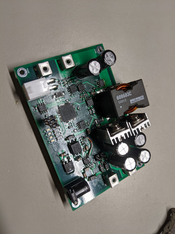
Okay, everything's installed. I had a few little hiccups, like picking a footprint with the wrong pitch (1.27 mm, needed 2.54 mm) for the programming header, so I got creative and attached a 2.54 mm header I had with wires. I also neglected the courtyard for the big inductor, so it hangs off the board. The two MOSFETs could use a little more space, but at least they're insulated to the heatsinks...
So this thing won't be passing vibe anytime soon. But, so far it seems okay electrically - as in, the housekeeping supply still puts out 5 V, and about 14.2 V for the gate driver. Nothing seems to be pulling it down, like a solder bridge or something. I should be able to get started on programming it, starting with a constant, open-loop PWM signal to the MOSFETs. Then I can look at RS485 comms, and proper control loops.
For those who've only seen bits and pieces of my postings on this, this circuit is just a buck converter. Or a boost converter, in the opposite direction. I just wanted to play around with one, and will probably revise the board in the future.
Basically, it's mean to work with a 12 or 24 VDC nominal bus on the low voltage side, and a 24 or 36 VDC bus on the high voltage side. (In other words, voltage you'd see from a 12, 24, or 36 VDC lead acid battery.) It's mostly to play around, but I intend to add extra logic to make it charge a higher voltage battery from a lower voltage one (or vice versa). Could also be used for photovoltaic maximum power point tracking (MPPT) I guess, but that's not the main intent right now.
#electronics #BuckConverter #PrintedCircuitBoard #kicad6 #PowerElectronics
#powerelectronics #kicad6 #printedcircuitboard #buckconverter #electronics
🎃 Forbidden Donut 🎃 · @toroidalcore
161 followers · 1702 posts · Server hackers.town
More parts soldered, but going to stop for the night.
🎃 Forbidden Donut 🎃 · @toroidalcore
161 followers · 1702 posts · Server hackers.town
Looks like it's working with about 37.5 V, from 3 12 volt #batteries. So not too bad. Once again, I have the shield just in case.
#electronics #PowerConversion #BuckConverter #PrintedCircuitBoard #LeadAcidBatteries #36v
#36v #LeadAcidBatteries #printedcircuitboard #buckconverter #PowerConversion #electronics #batteries
🎃 Forbidden Donut 🎃 · @toroidalcore
161 followers · 1702 posts · Server hackers.town
My buck converter board finally came. I might start to get this thing assembled this week, at least in stages - I want to make sure the housekeeping supply works (the buck converter that powers the buck converter), then get the microcontroller on. Then get the rest of it together, and maybe move some power.
I should have enough parts to build two of these, assuming I didn't do something horrendous that requires a redesign. Like accidentally build an efficient radio transmitter.
#buckconverter #powerelectronics #electronics #kicad6 #pcb
🎃 Forbidden Donut 🎃 · @toroidalcore
162 followers · 1702 posts · Server hackers.town
Okay, I managed to save some space. There's a couple things I think I want to check footprint-wise, mainly orientation of some diodes.
#electronics #kicad6 #buckconverter
🎃 Forbidden Donut 🎃 · @toroidalcore
162 followers · 1702 posts · Server hackers.town
Redoing this board a little bit to make it 100 mm long, down from 120. This is hopefully to save some cash when sending it to fab. There was a lot of unused space anyway.
#buckconverter #electronics #kicad6
🎃 Forbidden Donut 🎃 · @toroidalcore
162 followers · 1702 posts · Server hackers.town
So this board is about 2.5 inches by 5 inches, and will end up being four layers. That includes a main power/signal plane on top, a ground plane, a 5V plane, and an extra signal plane on the back. I haven't started routing it yet, and I may tweak the layout to space things out or make the board a little smaller.
#circuit #buckconverter #kicad6
🎃 Forbidden Donut 🎃 · @toroidalcore
162 followers · 1702 posts · Server hackers.town
The initial glob of components, which can hopefully be turned into a sane layout.
🎃 Forbidden Donut 🎃 · @toroidalcore
162 followers · 1702 posts · Server hackers.town
After another chunk of procrastination, it's kind of falling into place. Next step is to generate a BOM, then see what parts are unavailable and what to sub for them.
🎃 Forbidden Donut 🎃 · @toroidalcore
162 followers · 1702 posts · Server hackers.town
Rearranged this a little, I think I'll start routing this now.
This is just a buck converter I've been kicking around for a while, it's mostly just for practice, but if it works it should let me charge a 12 V battery from a 24 V battery. Or the other way around.